 Kia Rio: Shift Lever Removal
| Shift Lever Assembly Replacement
|
|
1. |
Remove the floor Interior console assembly.
(Refer to "Interior (Console)" in BD group)
|
|
2. |
Remove the heater duct (A).
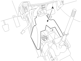
|
|
3. |
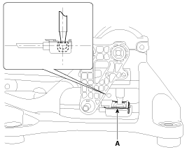
Remove the select cable assembly after removing select cable snap
pin (A) and clip (B).

|
|
4. |
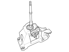
Remove the shift lever assembly (B) by removing the bolts (A-4ea).
Tightening torque:
8.8 ~ 13.7 N.m (0.9 ~ 1.4 kgf.m, 6.5 ~ 10.1 lb-ft)
|

|
|
5. |
Remove the shift lever assembly (B) by removing the clip (A).
|
|
•
Set securely.
|
| Select / Shift Cable Replacement |
|
1. |
Remove the floor Interior console assembly.
(Refer to "Interior (Console)" in BD group)
|
|
2. |
Remove the heater duct (A).

|
|
3. |
Remove the select cable assembly after removing select cable snap
pin (A) and clip (B).

|
|
4. |
Remove the shift lever assembly (B) by removing the bolts (A-4ea).
Tightening torque:
8.8 ~ 13.7 N.m (0.9 ~ 1.4 kgf.m, 6.5 ~ 10.1 lb-ft)
|

|
|
5. |
Remove the clip (A) from the shift cable assembly.
|
|
•
Set securely.
|


|
6. |
Remove the crash pad.
(Refer to "Interior (Crash pad)" in BD group.)
|
|
7. |
Remove the heater unit.
(Refer to "Heater (Heater unit)" in HA group.)
|
|
8. |
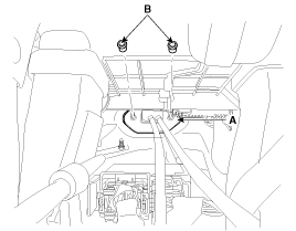
Remove the retainer (A) and nuts (B-2ea).
Tightening torque:
11.8 ~ 14.7 N.m (1.2 ~ 1.5 kgf.m, 8.7 ~ 10.8 lb-ft)
|

|
|
9. |
Remove the pins (A).
|
|
10. |
Remove the cable (B) from the cable bracket at manual transaxle
assembly side.
|
|
11. |
Remove the shift cable and select cable at cabin room.

|
|
12. |
Installation is the reverse of removal.
|
[Shift / Select Cable Installation Tips]
|
1. |
Installation the select and shift cable assembly (B) after removing
the pin (A).

|
|
2. |
Installation is the shift cable (A).
At this time, have to disconnect select cable.
|

|
3. |
Installation is the shift lever assembly (A).
Tightening torque:
8.8 ~ 13.7 N.m (0.9 ~ 1.4 kgf.m, 6.5 ~ 10.1 lb-ft)
|

|
|
4. |
Shift to the 3th gear position.
|
|
5. |
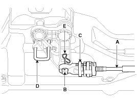
Insert the selected cable (A) to the shift lever assembly pin
(B).
|
|
6. |
You have to push in the adjuster (C).
|
|
7. |
Remove the neutral position pin (D).
|
|
8. |
Install the snap pin (E).
|
1. Shift lever knob
2. Shift lever assembly
3. Select cable assembly
4. Shift cable assembly
5. Retainer
...
1.
Check the select cable for proper operation and for damage.
2.
Check the shift cable for proper operation and for damage.
...
See also:
Special Service Tools
Tool (Number and name)
Illustration
Use
09411-1P000
Clutch disc guide
Installation of the clutch disc.
...
Special Service Tools
Tool (Number and Name)
Illustration
Use
09581-11000
Piston expander
Spreading the front disc brake piston
09580 - 0U000
Brak ...
26 Brake Control Solenoid Valve(26/B_VFS) Description
26 brake control solenoid valve(26/B_VFS) is attached to the valve body.
This variable force solenoid valve directly controls the hydraulic pressure
inside the 26 brake.
...
 Kia Rio: Shift Lever Removal


 Shift Lever Components
 Shift Lever Inspection