Kia Cee'd: IMS (Integrated Memory) / Schematic diagrams
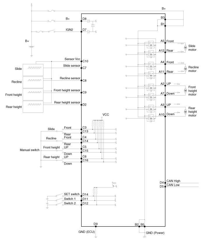
| Circuit Diagram |

| Input/Output Specification |
| Connector Pin Lay Out |

IMS input/output pin information
|
No |
Signal Name |
I/O |
Contents |
Remark |
|
A1 |
- |
- |
- |
|
|
A2 |
Front height motor up |
O |
Front height motor up output |
|
|
A3 |
Rear height motor up |
O |
Rear height motor up output |
|
|
A4 |
Recline motor front |
O |
Recline motor front output |
|
|
A5 |
Slide motor front |
O |
Slide motor front output |
|
|
A6 |
- |
- |
- |
|
|
A7 |
Front height motor down |
O |
Front height motor down output |
|
|
A8 |
- |
- |
- |
|
|
A9 |
- |
- |
- |
|
|
A10 |
Rear height motor down |
O |
Rear height motor down output |
|
|
A11 |
Recline motor rear |
O |
Recline motor rear output |
|
|
A12 |
Slide motor rear |
O |
Slide motor rear output |
|
|
B1 |
B+(Power) |
I |
Power B+ for operating motor |
|
|
B2 |
GND(Power) |
I |
Power GND for operating motor |
|
|
B3 |
B+(Power) |
I |
Power B+ for operating motor |
|
|
B4 |
GND (Power) |
I |
Power GND for operating motor |
|
|
B5 |
B+(Power) |
I |
Power B+ for operating motor |
|
|
C1 |
- |
- |
- |
|
|
C2 |
- |
- |
- |
|
|
C3 |
Slide front manual switch |
I |
Slide front manual switch input |
On : GND |
|
C4 |
Recline front manual switch |
I |
Recline front manual switch input |
On : GND |
|
C5 |
Front height up manual switch |
I |
Front height up manual switch input |
On : GND |
|
C6 |
Rear height up manual switch |
I |
Rear height up manual switch input |
On : GND |
|
C7 |
Slide motor sensor |
I |
Slide motor sensor input |
Pulse signal |
|
C8 |
Front height motor sensor |
I |
Front height input motor sensor |
Pulse signal |
|
C9 |
Front height motor sensor |
I |
Front height motor sensor input |
Pulse signal |
|
C10 |
Sensor Vcc(Seat) |
O |
VCC for operating sensor |
5V |
|
C11 |
- |
- |
- |
|
|
C12 |
- |
- |
- |
|
|
C13 |
Slide rear manual switch |
I |
Slide rear manual switch input |
ON : GND |
|
C14 |
Recline rear manual switch |
I |
Recline rear manual switch input |
ON : GND |
|
C15 |
Front height down manual switch |
I |
Front height down manual switch input |
ON : GND |
|
C16 |
Rear height down manual switch |
I |
Rear height down manual switch input |
ON : GND |
|
C17 |
- |
- |
- |
|
|
C18 |
- |
- |
- |
|
|
C19 |
- |
- |
- |
|
|
C20 |
- |
- |
- |
|
|
D1 |
- |
- |
- |
|
|
D2 |
Rear height sensor |
I |
Rear height motor sensor |
Pulse signal |
|
D3 |
- |
- |
- |
|
|
D4 |
CAN High |
I/O |
CAN |
|
|
D5 |
CAN Low |
I/O |
CAN |
|
|
D6 |
- |
- |
- |
|
|
D7 |
IGN1 |
I |
IGN1 input |
BAT |
|
D8 |
B+(ECU) |
I |
ECU power input |
BAT |
|
D9 |
GND(ECU) |
I |
ECU GND |
|
|
D10 |
- |
- |
- |
|
|
D11 |
Switch1 |
I |
Switch input |
|
|
D12 |
Switch2 |
I |
Switch input |
|
|
D13 |
- |
- |
- |
|
|
D14 |
SET switch |
I |
Switch input |
|
|
D15 |
- |
- |
|
|
|
D16 |
- |
- |
|
|
| Communication System |

 Components and components location
Component Location
1. Seat Memory Unit (IMS)
2. IMS control switch
3. IMS driver power seat control
...
 Description and operation
Description
system outline
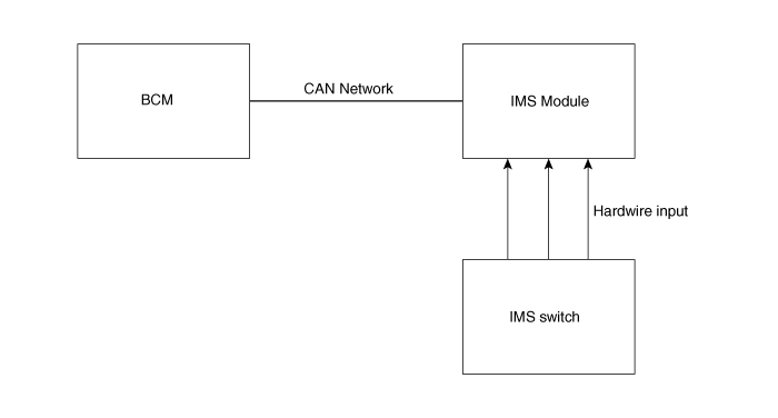
An optimal seat position set by a driver can be memorized in Power seat unit
by IMS SW, which enables restoration of seat position set by the ...
Other information:
Kia Cee'd JD Service Manual: Sunvisor Repair procedures
Replacement
•
Put on gloves to protect your hands.
•
Use ...
Kia Cee'd JD Owners Manual: Immobilizer indicator
Without smart key system
This indicator illuminates when the
immobilizer key is inserted and turned to
the ON position to start the engine.
At this time, you can start the engine.The
indicator goes out after the engine is running.
If this indicator blinks when the ignition
switch is in ...
