Kia Cee'd: Smart Key System / Smart Key Diagnostic Repair procedures
| Inspection |
| 1. |
Problem in SMART KEY unit input.
|
| 2. |
Problem in SMART KEY unit.
|
| 3. |
Problem in SMART KEY unit output.
|
| 1. |
SMART KEY unit Input problem : switch diagnosis
|
| 2. |
SMART KEY unit problem : communication diagnosis
|
| 3. |
SMART KEY unit Output problem : antenna and switch output diagnosis
|
| 1. |
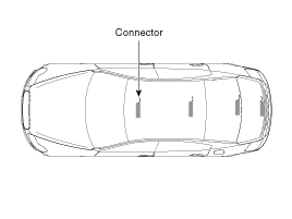
Connect the cable of GDS to the data link connector in driver side crash
pad lower panel, turn the power on GDS.
|
| 2. |
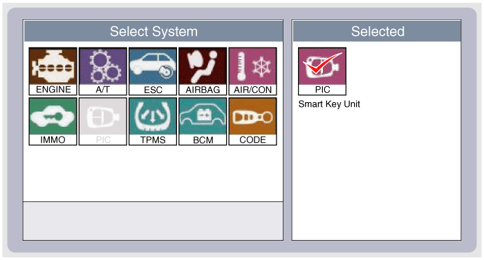
Select the vehicle model and then SMART KEY system.
|
| 3. |
Select the "SMART KEY unit".
|
| 4. |
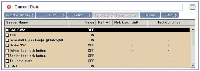
After IG ON, select the "Current data".
|
| 5. |
You can see the situation of each switch on scanner after connecting
the "current data" process.
|
| 1. |
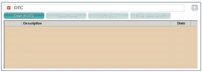
Communication diagnosis checks that the each linked components operates
normal.
|
| 2. |
Connect the cable of GDS to the data link connector in driver side crash
pad lower panel.
|
| 3. |
After IG ON, select the "DTC".
|
| 1. |
Connect the cable of GDS to the data link connector in driver side crash
pad lower panel.
|
| 2. |
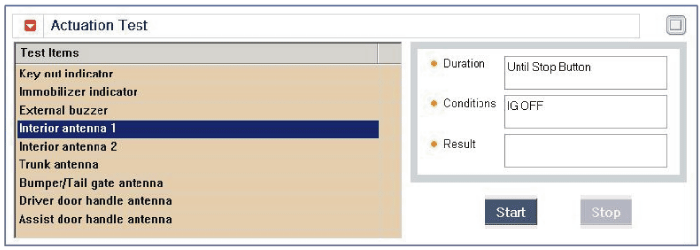
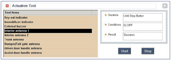
After IG ON, select the "ACTUATION TEST".
|
| 3. |
Set the smart key near the related antenna and operate it with a GDS.
|
| 4. |
If the LED of smart key is blinking, the smart key is normal.
|
| 5. |
If the LED of smart key is not blinking, check the voltage of smart
key battery.
|
| 6. |
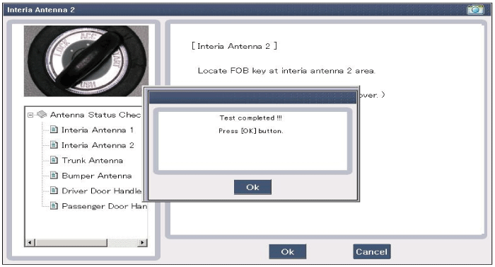
Antenna actuation
|
| 1. |
Connect the cable of GDS to the data link connector in driver side crash
pad lower panel.
|
| 2. |
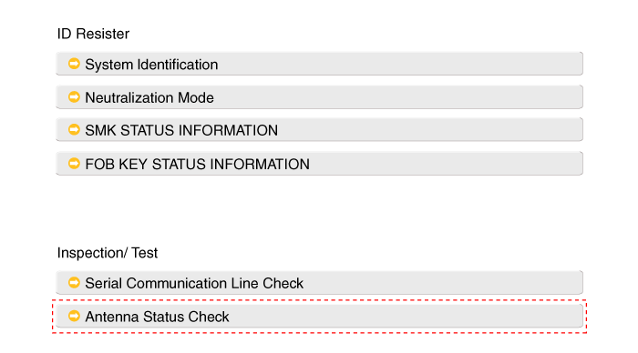
Select the "Antenna Status Check".
|
| 3. |
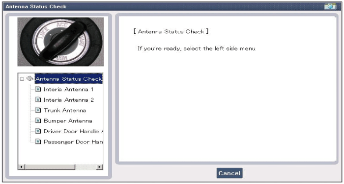
After IG ON, select the "Antenna Status Check".
|
| 4. |
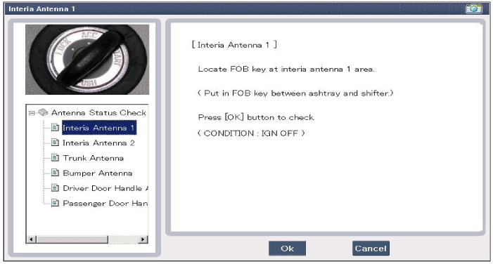
Set the smart key near the related antenna and operate it with a GDS.
|
| 5. |
If the smart key runs normal , the related antenna, smart key(transmission,
reception) and exterior receiver are normal.
|
| 6. |
Antenna status
|
| 1. |
Connect the cable of GDS to the data link connector in driver side crash
pad lower panel.
|
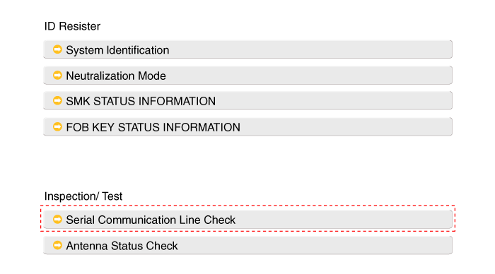
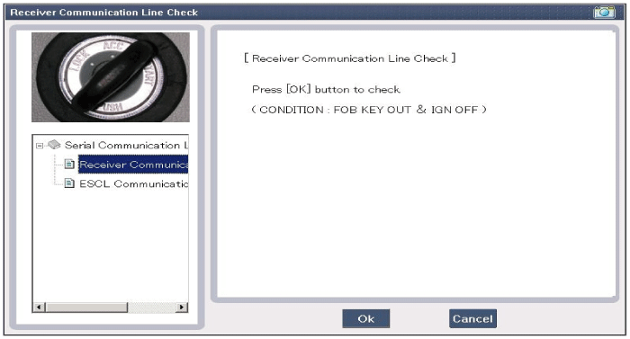
| 2. |
Select the "Serial Communication Line Check".
|
| 3. |
After IG ON, select the "Receiver Communication Line Check".
|
| 4. |
Check the serial communication line with a GDS.
|
| 5. |
If the smart key runs normal, the communication of smart key unit, exterior
receiver are normal.
|
| 6. |
If the smart key runs abnormal, check the following items.
|
| 1. |
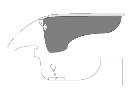
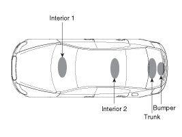
Set the smart key in the following shade area and check the IG ON.
|
| 2. |
If the ignition is ON, the antenna runs normal.
|
| 3. |
Check the interior antenna ignition mode.
|
| 4. |
Set the smart key in the following shade area and actuate the antenna.
Check the LED of smart key is blinking.
|
| 5. |
If the LED of smart key is not blinking, check the antenna in shade
area.
|
| 1. |
Connect the cable of GDS to the data link connector in driver side crash
pad lower panel.
|
| 2. |
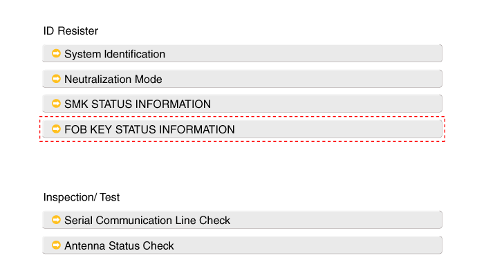
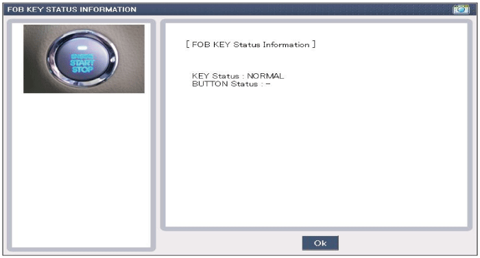
After IG ON, select the "FOB KEY STATUS INFO".
|
| 1. |
Connect the cable of GDS to the data link connector in driver side crash
pad lower panel.
|
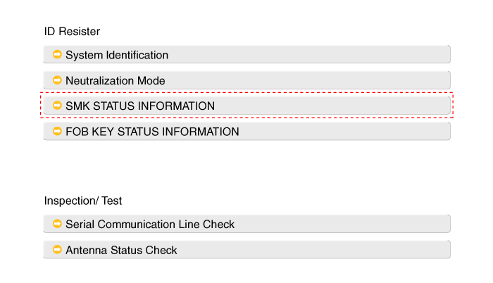
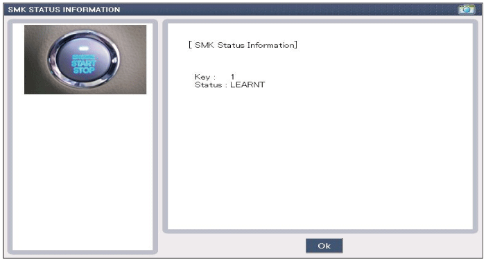
| 2. |
After IG ON, select the "SMK STATUS INFO".
|
| 1. |
Connect the cable of GDS to the data link connector in driver side crash
pad lower panel.
|
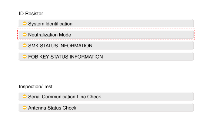
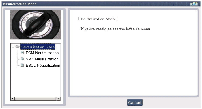
| 2. |
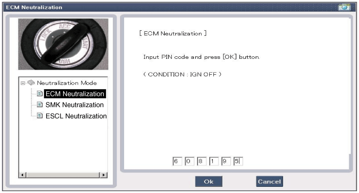
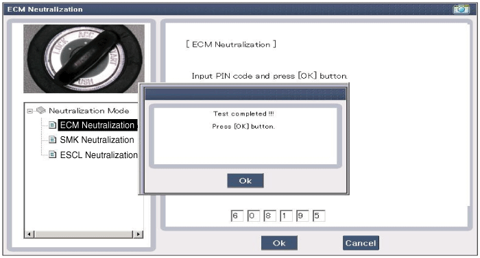
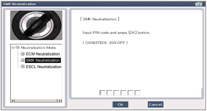
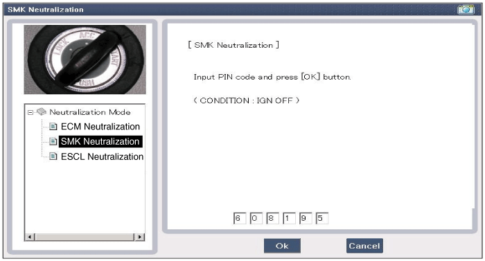
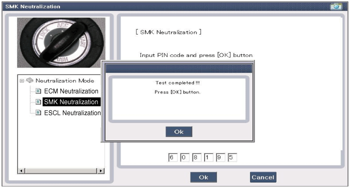
After IG ON, select the "Neutralization mode".
|
|
No |
Item name |
Unit |
|
1 |
SSB switch2 |
- |
|
2 |
ACC |
- |
|
3 |
IGN1 |
- |
|
4 |
Gear 'P' Position |
- |
|
5 |
Brake switch |
- |
|
6 |
FL Door Lock Button |
- |
|
7 |
FR Door Lock Button |
- |
|
8 |
Trunk/Tailgate Lid switch |
- |
|
9 |
Battery Voltage |
- |
|
10 |
Alternator Voltage |
- |
|
11 |
KEY out Indicator Lamp |
- |
|
12 |
Immobilizer Lamp |
- |
|
13 |
External Buzzer |
- |
|
No. |
Item name |
Condition |
|
1 |
Immo.indicator Lamp |
Ignition switch ON Engine off |
|
2 |
External Buzzer |
Ignition switch ON Engine off |
|
3 |
Interior Antenna 1 Active |
Ignition switch ON Engine off |
|
4 |
Interior Antenna 2 Active |
Ignition switch ON Engine off |
|
5 |
Trunk/Tailgate Antenna Active |
Ignition switch ON Engine off |
|
6 |
Bumper Antenna Active |
Ignition switch ON Engine off |
|
7 |
DRV DR Antenna Active |
Ignition switch ON Engine off |
|
8 |
AST DR Antenna Active |
Ignition switch ON Engine off |
 Description and operation
Description
The SMART KEY system is a system that allows the user to access and operate
a vehicle in a very convenient way. To access the vehicle, no traditional key
or remote co ...
 Smart Key Repair procedures
Smart Key
Smart Key Code Saving
1.
Connect the DLC cable of GDS to the data link connector in driver side
crash pad lower panel, turn the power on GDS.
...
Other information:
Kia Cee'd JD Service Manual: Engine Coolant Temperature Sensor (ECTS) Description and operation
Description
Engine Coolant Temperature Sensor (ECTS) is located in the engine coolant passage
of the cylinder head for detecting the engine coolant temperature. The ECTS
uses a thermistor that changes resistance with the temperature.
The electrical resistance of the ECTS d ...
Kia Cee'd JD Service Manual: Back-up Lamp Switch Description and operation
Description
•
Detects the shift operation to the reverse gear.
•
When the transaxle is in the reverse condition, the reverse shift rug
turns the back-up lamp switch onby pressing a shaft part of the switch.
...

