Kia Rio: Front Suspension System / Sub Frame
Repair procedures
| 1. |
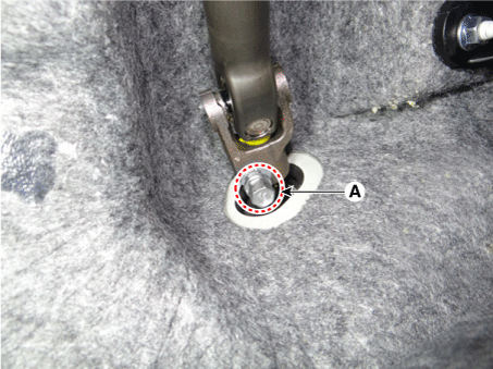
Remove the universal joint bolt (A).
|
Tightening torque :
32.4 - 37.3 N·m (3.3 - 3.8 kgf·m, 23.9 - 27.5 lb·ft)
|
| •
|
Keep the gear in the neutral range to prevent any damage
on the clock spring inner cable while handling the steering
wheel.
|
|
|
| 2. |
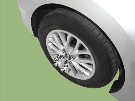
Remove wheel nuts, front wheel and tire from front hub.
|
Tightening torque:
107.9 - 127.5 N·m (11.0 - 13.0 kgf·m, 79.6 - 94.0 lb·ft)
|
|
Be careful not to damage the hub bolts when removing the front
wheel and tire.
|
|
| 3. |
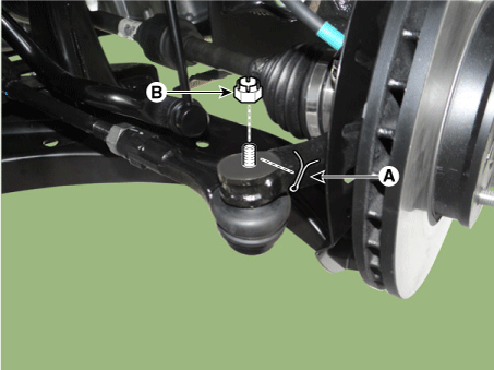
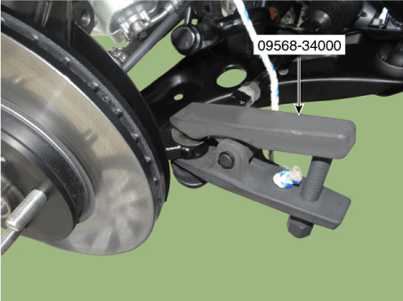
Remove the tie rod end ball joint from the knuckle by using the SST (09568-34000).
| (1) |
Remove the split pin (A).
|
| (2) |
Remove the castle nut (B).
|
| (3) |
Use the SST (09568-34000).
|
Tightening torque:
15.7 - 33.3 N·m (2.3 - 3.4 kgf·m, 16.6 - 24.6 lb·ft)
|
|
|
| 4. |
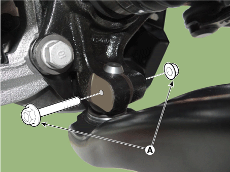
Remove the lower arm bolt and nut (A).
|
Tightening torque:
58.8 - 70.6 N·m (6.0 - 7.2 kgf·m, 43.4 - 52.1 lb·ft)
|
|
| 5. |
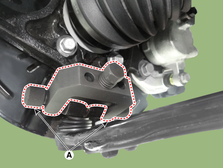
Remove the front lower arm from the front knuckle using the SST (0K545-A9100).
| (1) |
After removing bolts from the front knuckle, install and tighten
the sub body bolt (A) .
|
| (2) |
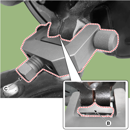
Input the sub body (B) between the front knuckle and the sub
body bolt.
|
| (3) |
Tighten the bolt (C) of the sub body to broaden the gap of the
front knuckle.
|
| (4) |
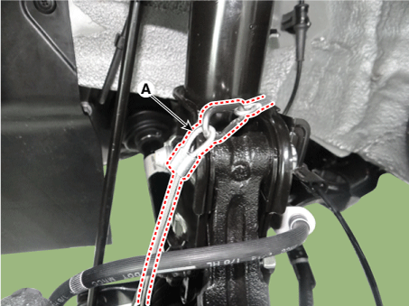
Install the safe wire (A).
|
| (5) |
Install the main body (A) between the front strut and the lower
arm.
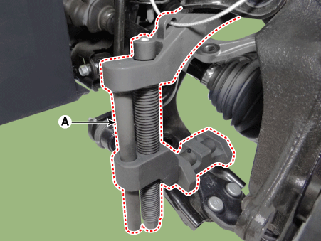
|
| (6) |
To avoid the main body coming off, install a fixing clamp (A)
beside the main body.
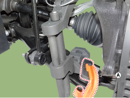
|
| (7) |
After installing a body (A), rotate the handle (B) clockwise
util the clamp is fixed on the lower arm.
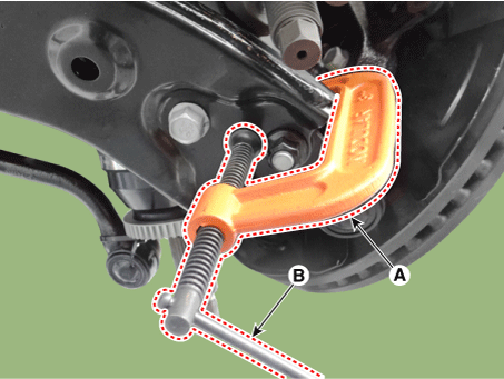
|
| (8) |
Tighten the main body bolt (A) slowly and remove the lower arm
from the front knuckle.
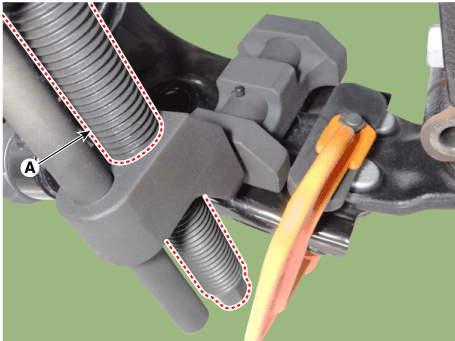
|
|
| 6. |
Remove the stabilizer link nut (A).
|
Tightening torque:
98.0 - 117.6 N·m (10.0 - 12.0 kgf·m, 72.3 - 86.7 lb·ft)
|
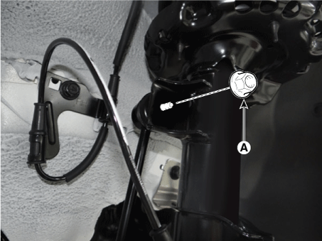
| •
|
When loosening the nut (A), fix the outer hexagon of
stabilizer bar link.
|
| •
|
Be careful not to damage the stabilizer link boots.
|
|
|
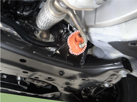
| 7. |
Remove the hanger.
|
| 8. |
Remove the roll rod bracket.
D 1.4 U2 TCI (Refer to Engine Mechanical System - "Engine Mounting")
G 1.0 T-GDI (Refer to Engine Mechanical System - "Engine Mounting")
G 1.2 MPI (Refer to Engine Mechanical System - "Engine Mounting")
G 1.4 MPI (Refer to Engine Mechanical System - "Engine Mounting")
|
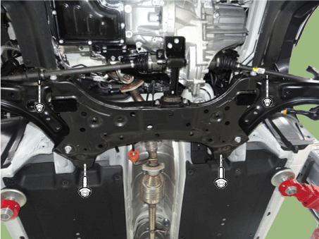
| 9. |
Loosen the bolts & nuts and then remove the sub frame (A).
|
Tightening torque:
176.5 - 196.1 N·m (18.0 - 20.0 kgf·m, 130.2 - 144.7 lb·ft)
|
|
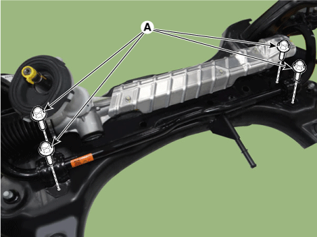
| 10. |
Loosen the bolts (A) and then remove the stabilizer bar assembly.
|
Tightening torque:
44.1 - 53.9 N·m (4.5 - 5.5 kgf·m, 32.5 - 39.8 lb·ft)
|
|
| 11. |
Loosne the heat protector bolts and then remove the heat protector.
|
Tightening torque:
6.9 - 10.8 N·m (0.7 - 1.1 kgf·m, 5.1 - 8.0 lb·ft)
|
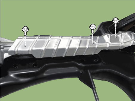
|
| 12. |
Loosen the gear box mounting bolts (A) and then remove the gear box.
|
Tightening torque:
88.2 - 107.8 N·m (9.0 - 11.0 kgf·m, 65.0 - 79.5 lb·ft)
|
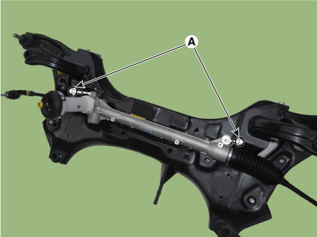
|
| 13. |
Install in the reverse order of removal.
|
| 14. |
Check the wheel alignment.
(Refer to Tires/Wheels - "Alignment")
|
Repair procedures
Removal
1.
Remove the universal joint bolt (A).
Tightening torque :
32.4 - 37.3 N·m (3.3 - 3.8 kgf·m, 23.9 - 27.5 lb·ft)
...
Components and components location
Components
[Drum Type]
1. Torsion beam axle
2. Rear spring
3. Rear drum brake disc
[Disc Type ...
Other information:
■ Type A
■ Type B
To turn on the high beam headlights, push the lever away from you. Pull it back
for normal (low beam) position. The high beam indicator light will illuminate when
the headlight high beams are switched on.
To prevent the battery from being discharged, do not leave the ...
Repair procedures
Inspection
1.
Check the tire pressure.
15(inch) : 230 kPa (33 psi)
16(inch) : 230 kPa (33 psi)
17(inch) : 230 kPa (33 psi)
Tire Rotation
Checking For Pull And
Wander
If the steering pulls to one side, rotate the tires accordi ...
 Front Stabilizer Bar
 Rear Suspension System


