 Kia Rio: Schematic Diagrams
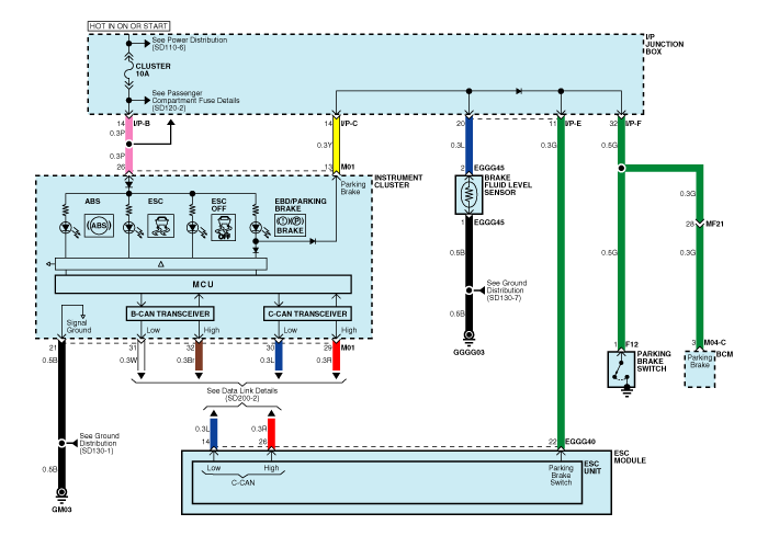
Circuit Diagram - ESC (1)

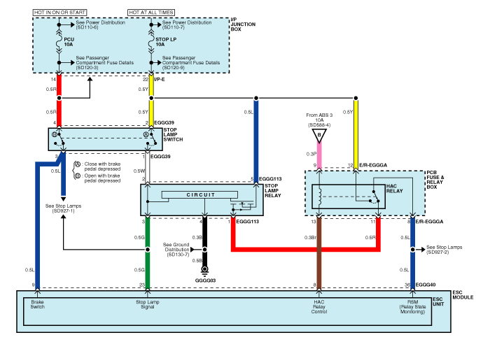
Circuit Diagram - ESC (2)

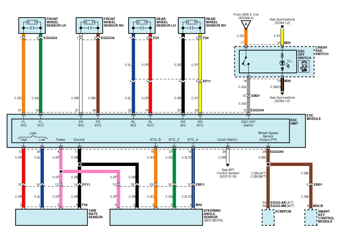
Circuit Diagram - ESC (3)

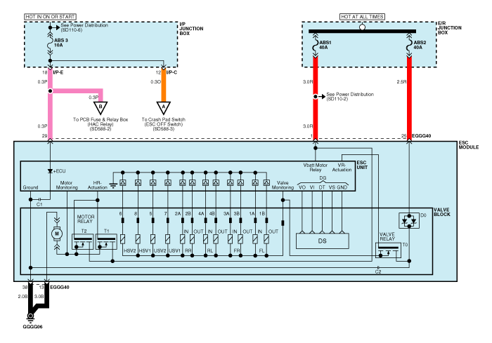
Circuit Diagram - ESC (4)

ESC connector input/output

| Connector Terminal |
Specification |
Remark |
|
| No |
Description |
||
| 29 |
IGNITION1(+) |
High level of wake up voltage : 4.5V < V < 16.0V Low level of wake up voltage : V < 2.4V Max. current : I < 50mA |
|
| 25 |
POS. BATTERY 1.(SOLENOID) |
Over voltage range : 17.0 ± 0.5V Operating voltage range : 10.0 ± 0.5V < V < 16.0 ± 0.5V Low voltage range : 7.0 ± 0.5V < V < 9.5 ± 0.5V Max. current : I < 40A Max. leakage current : I < 0.25mA |
|
| 1 |
POS. BATTERY 2.(MOTOR) |
Operating voltage range: 10.0 ± 0.5V < V < 16.0 ± 0.5V Rush current : I < 110A Max current : I < 40A Max leakage current : I < 0.25mA |
|
| 38 |
GROUND |
Rated current : I <550mA Max. current: I < 40A |
|
| 13 |
PUMP MOTOR GROUND |
Rush current : I < 110A Max current : I < 40A |
|
| 11 |
SENSOR GROUND |
Rated current : I <250mA |
|
| 4 |
SENSOR POWER |
Max current Capability : I < 250mA Max voltage : V_BAT1 -0.8V |
|
| 23 |
BRAKE LIGHT SWITCH |
Input voltage (Low) : V < 2.0V Input voltage (High) : V > 6.0V Max. Input current : I < 3mA (@12.8V) |
|
| 10 |
ESC ON/OFF SWITCH |
||
| 9 |
BRAKE SWITCH |
||
| 22 |
PARKING BRAKE SWITCH |
Input voltage (Low) : V < 2.0V Input voltage (High) : V > 6.0V Max input current : I < 5mA (@12.8V) |
|
| 35 |
CLUTCH SWITCH |
||
| 28 |
SENSOR FRONT RIGHT OUTPUT |
External pull up resistance :1 KΩ < R Output duty : 50 ± 20% |
|
| 14 |
CAN BUS LINE(LOW) |
Max. Input current : I < 10mA |
|
| 26 |
CAN BUS LINE(HIGH) |
||
| 18 |
SENSOR FRONT LEFT POWER |
Output voltage : V_BAT1 -0.6V ~ V_BAT1 -1.1V Output current : Max 30mA |
|
| 34 |
SENSOR FRONT RIGHT POWER |
||
| 19 |
SENSOR REAR LEFT POWER |
||
| 33 |
SENSOR REAR RIGHT POWER |
||
| 31 |
SENSOR FRONT LEFT SIGNAL |
Input current LOW : 5.9 ~ 8.4mA Input current HIGH : 11.8 ~ 16.8mA Frequency range : 1 ~ 2,500Hz Input duty : 50 ± 10% |
|
| 21 |
SENSOR FRONT RIGHT SIGNAL |
||
| 32 |
SENSOR REAR LEFT SIGNAL |
||
| 20 |
SENSOR REAR RIGHT SIGNAL |
||
| 12 |
CAN SENSOR LINE (HIGH) |
Max. input current : I < 10mA |
|
| 24 |
CAN SENSOR LINE (LOW) |
||
| 8 |
HAC RELAY DRIVE |
Max. current : I < 180mA Max output voltage : V< 1.2V |
|
| 36 |
HAC RELAY STATE MONITORING |
Input voltage (Low) : V < 2V Input voltage (High) : V > 6V Max input current : I < 10mA (@12.8V) |
|
| 11 |
STEERING ANGLE SENSOR PHASE A |
Input duty (STG A, STG B) : 50 ± 10% Phase Difference (STG A, STG B) : 2 ± 0.6 deg High voltage : 3.0V < V_H < 4.1V Low voltage : 1.3V < V_L < 2.0V |
without MDPS |
| 1 |
STEERING ANGLE SENSOR PHASE B |
||
| 27 |
STEERING ANGLE SENSOR PHASE Z |
||
 ESC Operation Mode
 Failure Diagnosis
Record your key number
The key code number is stamped on the key code tag attached to the key set. Should
you lose your keys, this number will enable an authorized Kia dealer to duplicate
the keys easily.
After reco ...
Starter: Removal and Installation
1.
Disconnect the battery negative terminal.
2.
Remove the air duct and air cleaner assembly. (Refer to EM group)
3.
...
Seat belt restraint system
Seat belts are designed to bear upon the bony structure of the body, and should
be worn low across the front of the pelvis or the pelvis, chest and shoulders, as
applicable; wearing the lap sectio ...