Kia Rio: Rear Suspension System / Rear Torsion Beam Axle
Components and components location
| Components |

| 1. Torsion beam |
Repair procedures
| Removal |
| 1. |
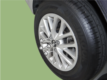
Remove wheel nuts, rear wheel and tire from rear hub.
|
| 2. |
Remove the rear axle assmebly. (Refer to Brake System - "Rear Disc Brake") (Refer to Brake System - "Rear Drum Brake") |
| 3. |
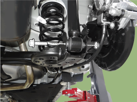
Loosen the shock absorber lower bolt.
|
| 4. |
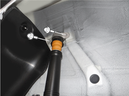
Loosen the bolts and then remove the rear shock apsorber.
|
| 5. |
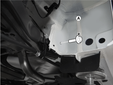
Loosen the bolts (A) and then remove the torsion beam.
|
| 6. |
Install in the reverse order of removal. |
| Replacement |
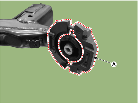
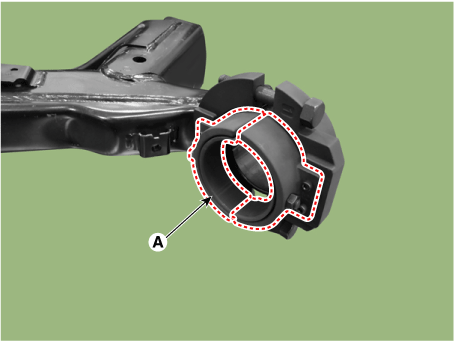
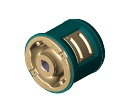
CTBA (Coupled Torsion Beam Axle) bush
| Plastic type |
|
| 1. |
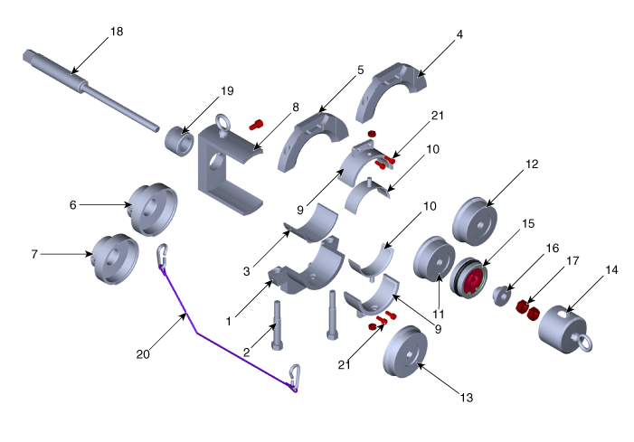
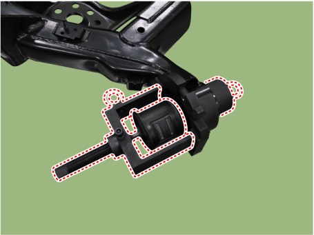
Using a SST (09551-AL100), replace the CTBA (Coupled Torsion Beam Axle) bush.
|
| 2. |
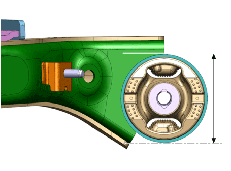
Measure outer diameter of the torsion beam axle. Outer diameter of the torsion beam axle has 78 mm (3.0709 in) and 84 mm (3.3071 in) two types.
|
| 3. |
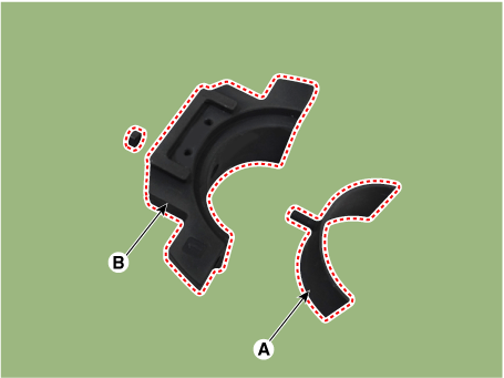
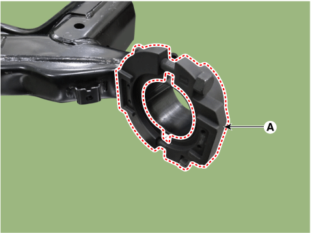
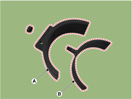
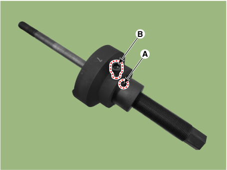
Install the beam clamp adapter (A) on beam clamp A (B).
|
| 4. |
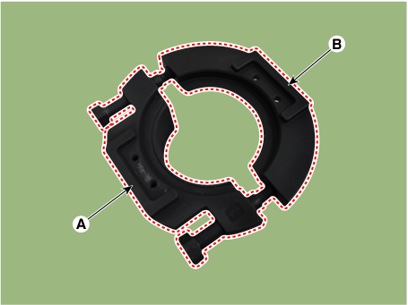
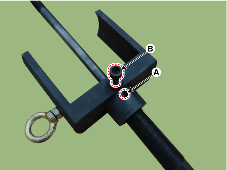
Pre-install the beam clamp A (A) and the beam clamp C (B) with bolt.
|
| 5. |
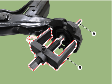
Assemble the bolt after installing the beam clamp (A) on the beam pipe accurately.
|
| 6. |
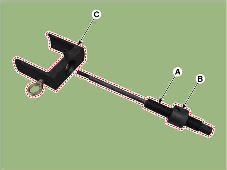
Assemble the main bolt (A) and the main nut (B), then insert it into the beam clamp support (C).
|
| 7. |
Align the main nut hole (A) and bolt (B) exactly, then assemble them.
|
| 8. |
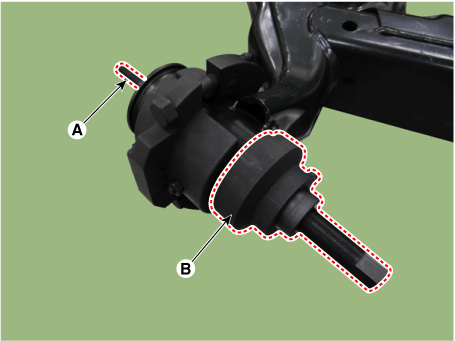
Assemble the beam support (B) and the beam clamp guide by aligning them after inserting the main bolt (A) into bush hole.
|
| 9. |
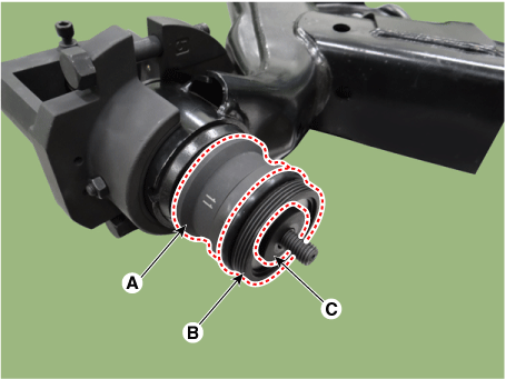
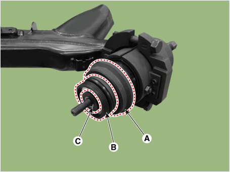
Install it on the main bolt by the order of remover adapter A (A), bearing (B) and washer (C).
|
| 10. |
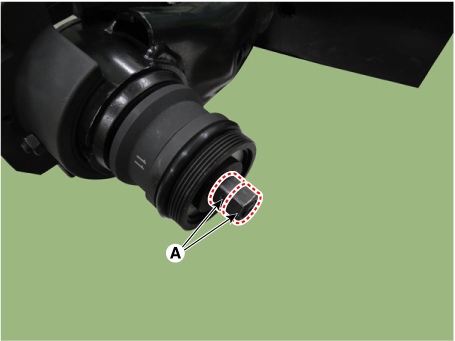
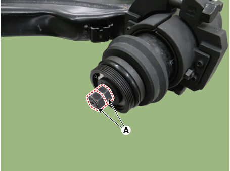
Pre-install the 2 nuts (A).
|
| 11. |
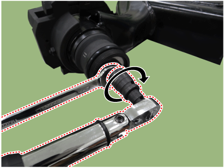
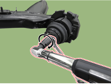
Install by double nut method with spanner and torque wrench.
|
| 12. |
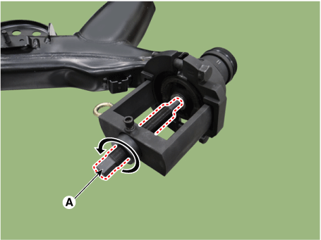
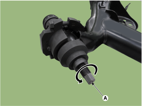
Install SST properly by rotating the main bolt (A) counterclockwise.
|
| 13. |
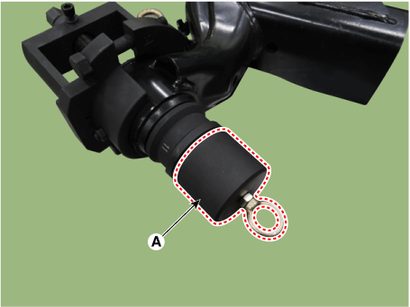
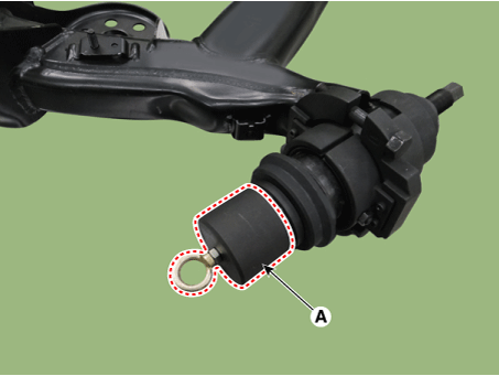
Install the safety cap (A).
|
| 14. |
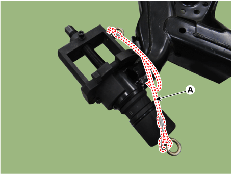
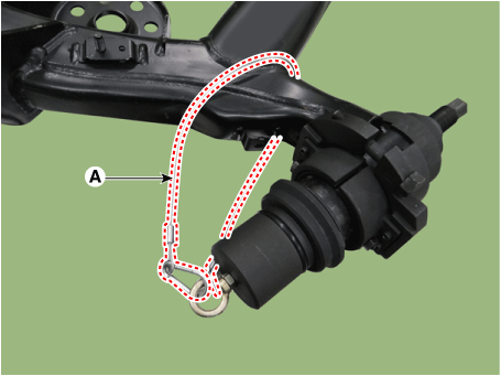
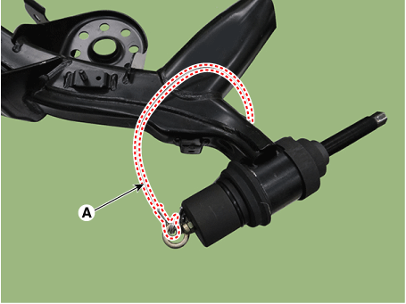
Connect the safety wire (A) by winding once around torsion beam axle.
|
| 15. |
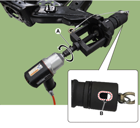
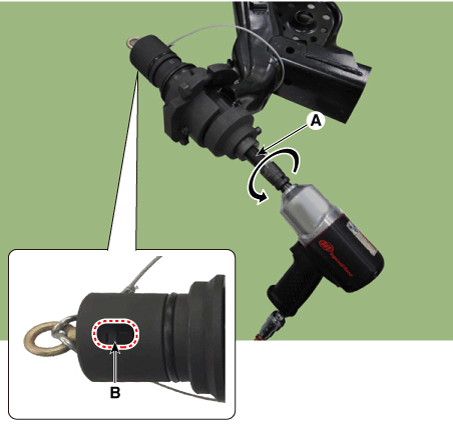
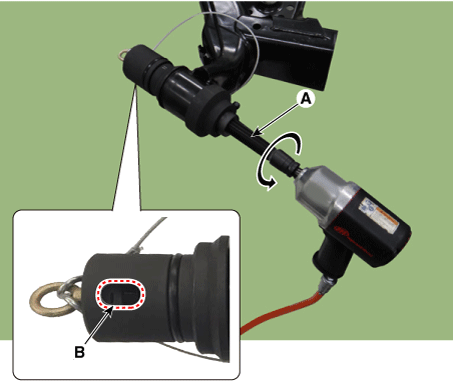
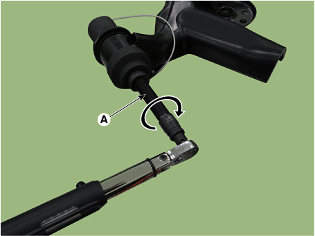
Remove the bush by rotating the main bolt (A) counterclockwise using by air impact wrench. In this procedure check if the nut is loosening or not by eyesight through the hole of cap (B). And if the nut is loosening then re-tighten by regulated torque.
|
| 16. |
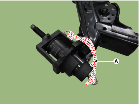
Disassemble the safety wire (A) after fully removal of the bush.
|
| 17. |
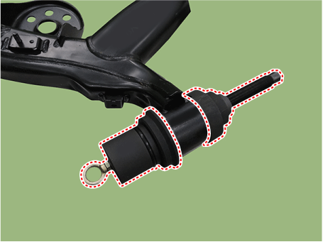
Remove the bush and SST from the torsion beam axle.
|
| 18. |
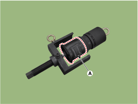
Remove the bush (A) by disassembling of the SST.
|
| 19. |
Install the bush guide B (B) on the bush guide A (A).
|
| 20. |
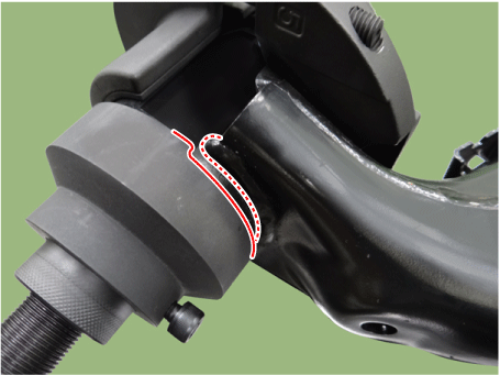
Install the bush guide (A) on the beam clamp.
|
| 21. |
Operate the procedure after pre-heating outer side of a new bush with heating gun about 40 - 60 °C (104 - 140 °F).
|
| 22. |
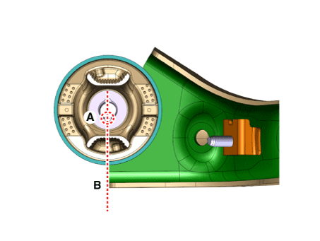
Install a new bush by aligning the groove of bush (A) and the lower section (B) of the torsion beam axle.
|
| 23. |
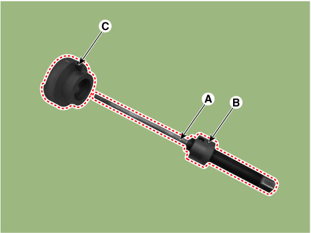
Assemble the main bolt (A) and the main nut (B), then insert them into the Installer adapter B (C).
|
| 24. |
Align the main nut hole (A) and volt (B) exactly, then assemble them.
|
| 25. |
Install the installer adapter (B) by inserting the main bolt (A) into the bush hole.
|
| 26. |
Install it on the main bolt by the order of installer adapter C (A), bearing (B) and washer (C).
|
| 27. |
Pre-install two nut (A).
|
| 28. |
Install by double nut method with spanner and torque wrench.
|
| 29. |
Install SST properly by rotating the main bolt (A) counterclockwise.
|
| 30. |
Install the safety cap (A).
|
| 31. |
Connect the safety wire (A) by winding once around torsion beam axle.
|
| 32. |
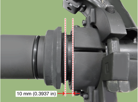
Install until it has 10 mm (0.3937 in) gap between the bush and the end edge of bush guide by rotating the main bolt (A) counterclockwise with air impact wrench. In this procedure check if the nut is loosening or not by eyesight through the hole of cap (B). And if the nut is loosening then re-tighten by regulated torque.
|
| 33. |
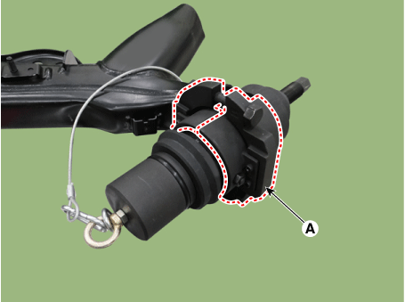
Remove the beam clamp (A).
|
| 34. |
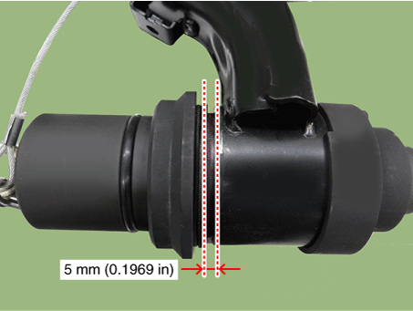
Install until it has 5 mm (0.1969 in) gap between the bush and torsion beam axle by rotating the main bolt (A) counterclockwise with air impact wrench. In this procedure check if the nut is loosening or not by eyesight through the hole of cap (B). And if the nut is loosening then re-tighten by regulated torque.
|
| 35. |
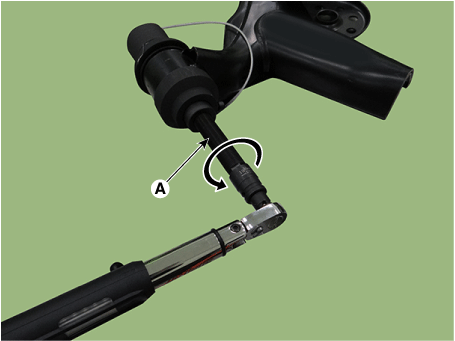
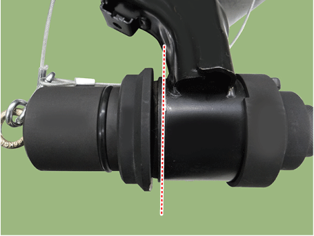
Rotate the main bolt counterclockwise until the bush and the end of the torsion beam are matched by using a hand wrench.
|
| 36. |
Release pressured tools by rotating the main bolt (A) clockwise after fully installation of the bush.
|
| 37. |
Disassemble the safety wire (A).
|
| 38. |
Remove the SST from the torsion beam axle.
|
 Rear Coil Spring
Repair procedures
Removal
1.
Remove wheel nuts, rear wheel and tire from rear hub.
Tightening torque:
107.9 - 127.5 N·m (11.0 - 13.0 kgf·m, 79 ...
 Tires/Wheels
...
Other information:
Kia Rio 2017-2020 YB Service Manual: Front Door Window Glass
Components and components location Component Location 1. Front door window glass Repair procedures Replacement Put on gloves to protect your hands. ...
Kia Rio 2017-2020 YB Service Manual: Transaxle Oil Temperature Sensor
Specifications Specification Item Specification Type *NTC thermistor Temp.[(°C)°F] / Resistance (kΩ) (-40)-40 / 139.5 (-20)-4.0 / 47.4 (0)32.0 / 18.6 ...

